10A. Workshop premises with IR detector and acoustic auxiliary detector
50 Hz or non-dimmable HF operating devices
Svenskt patent nr. 9201493-5, English patent No. 0659329
| The premises
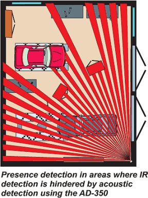
Workshop premises with screening interior fittings and screening objects that are moved around in the premises. Light sources This application shows an example of fittings with 50 Hz choke operation or non-dimmable HF operating devices. Positioning of detectors Positioning of IR detectors must be such that the fields of detection are passed through at right angles when entering (see illustration below). Control system By combining two different physical detection principles, namely passive IR and acoustic detection within a specific frequency range, it is possible to increase detection capacity in areas with screening objects and interior fittings. Note that only one IR detector can be connected in this application. This combination of an IR detector with an AD-350 acoustic detector is a special solution designed to eliminate unnecessary lighting due to occasional sound disturbances. |
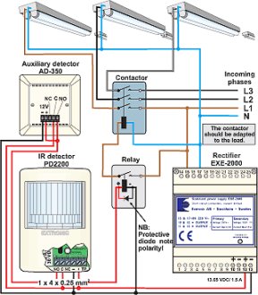
So the acoustic detector can start functioning and help the IR detector keep the lighting switched on in the event of presence, entry into the area registered by the IR detector is first required. The acoustic detector then registers sound in the relevant frequency range and helps keep the lighting switched on. The installation is switched off when the presence has ceased and the delay time has expired in the detector that last registered motion. Connection should be in accordance with the example below. Note the connection of the 12 VDC feed to the acoustic auxiliary detector.
Information for current budget
|


