2E. Hospital corridor with passive IR detectors
Dimmable HF operating devices, ‘Dynamic lighting control’, four levels and time switch
| Premises
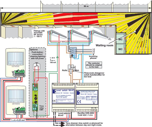
This application shows a long hospital corridor in which there are no concealed doors and the doors are often open. The corridor is used very frequently during certain periods of the day, i.e. when there are a lot of transits, and a system with Dynamic lighting control has thus been installed. Light sources The fittings in this garage have dimmable HF operating devices with analogue control (1 – 10 V). Positioning of detectors To achieve optimum detection and a high level of comfort it is important for detectors to be mounted in the correct position. This is particularly important with corridor solutions. Unfortunately one far too often sees detectors aimed at doors and entrances, thus adversely affecting detection. The optimum direction of detection is when the fields of recognition are crossed at 90°, and the poorest detection is achieved with motion in line with the fields of recognition in either direction. Because of this, a detector using a lens with a 90° opening angle must be selected. It must be mounted in a corner in front of the door so that it is not obscured when the door opens, and must be at the correct height (1.6 – 1.9 m in corridors). See Application 2B for instructions regarding positioning of the detectors. Control system With new buildings or renovations where there is a possibility of selecting fittings with dimmable operating devices, the installation must be in accordance with the principle ‘Dynamic lighting control’. The technology can be used with control involving either acoustic or IR detectors (see wiring diagram below). With NV-4T, dimmable fluorescent-tube fittings can be controlled at four light levels. Information for current budget
|
The most important advantages attained using Dynamic Control are as follows:
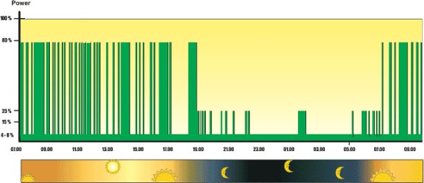
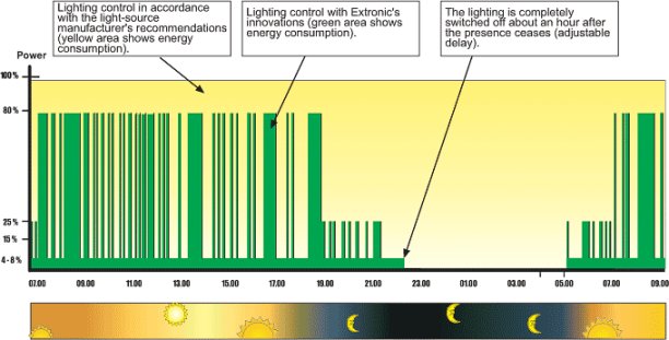
With the aid of a time channel from the existing system, a time switch or a light sensor, the lighting alternates between a ‘day’ program and a ‘night’ program in NV-4T. During presence in the daytime the light level is adjusted to about 80 per cent, and after nightfall the level is about 30 per cent. This creates a muted and pleasant light in the evening and at night that does not unnecessarily disturb sleeping patients. The energy saving is also about 20 per cent during daytime operation and about 70 per cent in the evenings and at night with activated lighting. When the presence ceases (daytime and night-time) the lighting is first dimmed down to basic light of about 2 per cent, and after 1 – 2 hours it is completely switched off when the three-mode changeover switch is in ‘Auto’ mode. This also eliminates no-load losses. When the changeover switch is in ‘Man’ mode the basic light is never switched off. When the changeover switch is in ‘Zero’ mode the fittings are dead. This is used as the service mode (see diagram on next page). As an option the lighting can be switched on manually with full power, e.g. in the event of evacuation or cleaning. For this function a push-button and a time relay are connected in accordance with coupling example below. The time relay is used to reconnect the lighting control after the set time.Installation of the detectors should be using the simplest possible cable, Type EKKX 1 x 4 x 0.25 mm2. All detectors should be connected in parallel with the rectifier EXE-2000, even if they form part of different areas. Regarding adjustment of the IR detectors one is referred to the manual enclosed with the detector. |
||||||||||||||||||
 |
|||||||||||||||||||
 |
|
||||||||||||||||||
| Daylight-related lighting control with NV-4T in hospital corridor Evening and night shift with muted lighting The yellow area represents energy consumption without lighting control. |
|||||||||||||||||||
 |
|||||||||||||||||||
| Daylight-related lighting control with NV-4T in hospital corridor Ward that closes at 9pm |
|||||||||||||||||||
 |
|||||||||||||||||||


